The 10,000 Mile Valve Job and Search for a Little More Torque
By Peter Pleitner
Five hundred miles after replacing the camshaft — on a highway nearing home from vintage races at Put-in Bay, Ohio while enjoying my new fifth gear and tires in my 1948 MGTC with 10k miles on the restored odometer — it suddenly started to demand all the travel the go pedal had left to maintain 65 to 70 mph. I started looking for signs of overheating, suspecting ignition retardation due possibly to a loose clamp around the distributor because it happened before — negative. Eventually 65 mph was all I got, then 60. Lucky by then I was close to my home exit.

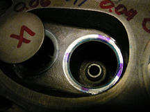
Photo #1
In the garage I poked around under the bonnet, principally checking for the usual faults — ignition system and fuel supply. When I finally started looking for a deeper cause with my leak-down tester and the valve cover off, everything measured perfect until I got to cylinder #4 — it maintained only 60% of input air pressure. Fearing worst case, a broken compression ring, I squirted about one cc of oil via the spark plug hole against the opposite cylinder wall with the piston about an inch or so from TDC with both valves closed. After allowing time for the oil to encircle the piston, I got the same 60% reading, whew. Then with my ear near the tailpipe I confirmed that the exhaust valve was hissing compressed air. At least that meant the engine didn't have to come out again.
Two years with other complications and two other project cars later I finally removed that cylinder head on the MGTC, leaving the exhaust manifold, thermostat housing, and radiator on the car. What I expected to find was a visibly damaged or burnt valve, not so, yeah. What I finally discovered after removing the exhaust valve was a big flake of carbon peened onto the valve's wide seating surface. The valve couldn't seal. If it had been a high performance engine it very well might have "flame-cut" a notch into the valve head. Much of this cylinder's power stroke squirted right past this exhaust valve. And it got much hotter than the other exhaust valves. The evidence is the dark color of the wide sealing surface that extends just shy of the valve head's margin in Photo #1 (above).
Diagnosis: My Italian tune up loosened some of the carbon on my flat-topped pistons because my head was bone stock with wide (ancient style) seat contact, like 0.120 inch or 3 mm wide. A tough piece of carbon didn't get crunched by the valve's seating pressure. In Photo #1 you can just make out this carbon flake at about 4 o'clock on the dark banded seating surface of the exhaust valve's head.
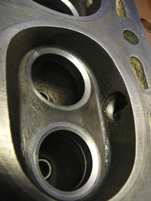
Photo #2
First thing I did was make a little aluminum scraper and found a small soft nozzle for my vacuum cleaner to remove carbon from the pistons. I now suspect that low compression increases carbon deposits. I rebuilt this engine over thirty years ago when we still had a little lead and no alcohol in our gasoline, and finished the car ten years later. It ran great, including four 1k and 2k miles tours with long stretches at around 4200 rpm. At Watkins Glen, it could keep up with a couple of 1500 TFs pulling uphill. But now is the time to install hardened exhaust seats and new guides (cheap) and important because they center all machining. That decided, this is what I was able to get from a local and good auto machine shop that rebuilds everything from tractors to Audis — a good durable valve job (as shown in Photo #2). But oh those steps and edges around the seats are perfect for reducing what little torque this XPAG can muster. I decided I will not let them subtract one foot pound of torque and further inspection revealed that I should be able to easily do a little port improvement too and add a few foot pounds. Experience with other engine work made me optimistic that I could do my head a big favor. At least I would end up with an improvement — more like an engine prepared by the factory's shop before road tests by magazines in the old days.
The big boys use a flow bench to test and measure their work and progress toward optimal performance. Here are the "shade-tree" principles I follow and apply at home with hand tools:
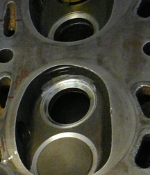
Photo #3
Flow of a liquid or gas follows Newtonian principles of physics which one of my professors derisively said can be learned in the gutter while watching water flow in the street. I think that everybody today can grasp the concept of streamlining and that any lumps or edges disturbs the airflow. When a surface breaks at an angle greater than 15 degrees, eddies begin to form downwind as velocity increases. Eddies are stationary circulations in a moving fluid and they constrict flow. Imagine looking down on a rock in a shallow stream (a two dimensional view). Eddies form downstream of it on either side. They force the water coming from upstream around a larger obstruction than the rock itself.
First I used my little Dremel tool spinning a 1/8 inch carbine ball burr and a thin (0.03 inch thick) round steel washer or shim to protect the valve seats (until I got steady enough using two hands) to open up and blend the cast iron between the seats and adjacent chamber walls, as can be seen in Photo #3 (right). Cast iron is as soft as cold butter when you are using sharp carbide burrs. I worked around the ends of the chambers like a dentist, opening up the space a little between where the valve heads would be when open and the chamber wall. Then I worked my way down to remove that disturbing step next to the seating surface. Here I used that shim washer to protect the seat from the burr catching and walking off. Since about 20% of the circumference of the valves in this head are shrouded by the chamber wall, just a little improvement here leads to easy gains in flow and volume. Also, it is important to realize that greater volume, achievable during the early part of a valve opening, occurs again while it is closing. This creates a more potent signal (pulse or sharper wavefront) which is the only thing that a carburetor can respond to. And before the valve closes completely, higher flow helps to maintain the velocity of flow from the carburetor which benefits the next cylinder in the firing order.
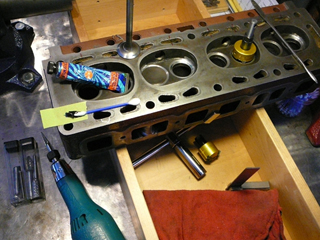
Photo #4
This knowledge — plus the necessary tools which I acquired since the last time I rebuilt this engine — now finally comes in handy. So it was natural to recognize and decide that those little step-downs around the seats are not helpful and likely the equivalent to hitching a little trailer for the XPAG to pull. My objective is to help the cylinders ingest as much fuel/air mixture as possible. When ignited, it is the potency of this charge on the piston (mean effective pressure) that determines how much torque is produced by the crankshaft. Horsepower is calculated from torque as a function of time, rpm, or how fast the work can be done. It responds more to improvements to the exhausting part of the combustion cycle. Exhaust that doesn't get out will restrict the amount of, and pollute the incoming charge, as rpm increases.
So, since my XPAG is a civilian, I decided to detail the intake port more to boost torque and I did not do as much on the exhaust side where I think more horsepower could be gained. But since I am not using a tubular exhaust header, nor larger valves, I decided to simply do a good job in shaping and positioning each three-angle valve seat.
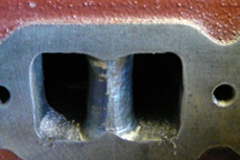
Photo #5b (After)
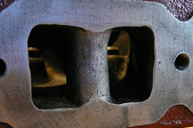
Photo #5a (Before)
Next, I stepped up in tool size by using my Makita die grinder, plugged into a router speed controller, to spin much larger carbide burrs, as shown in Photo #4 (above). I removed edges from the underside of the hardened valve seat implants, a few edges left by casting core shifts, and to create a more "ship's prow" shape on the two blunt bosses separating the "siamesed" intake ports where they face the incoming air/fuel mixture. I tackled making this shape, as seen in Photo #5b, after I marked a center line and inserted a snug fitting rod into the stud hole passing through it, to help me visualize where the casting would be getting uncomfortably thin if I shaved away more iron. I didn't think eddies form on the backside of this bridge because it felt to be well tapered to an edge. I deemed the rest of the ports good enough as is.